Gate Valve Dimensions
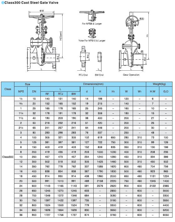
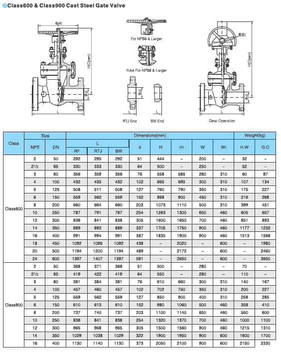
The tables show the dimensions and weights of API 600 gate valves (bolted bonnet / rising stem)
CLASS 150LB-2500LB
Dimensions in inches (millimeters)
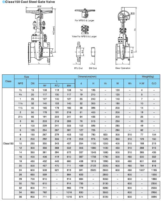
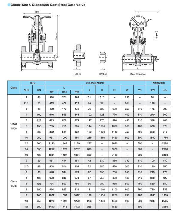
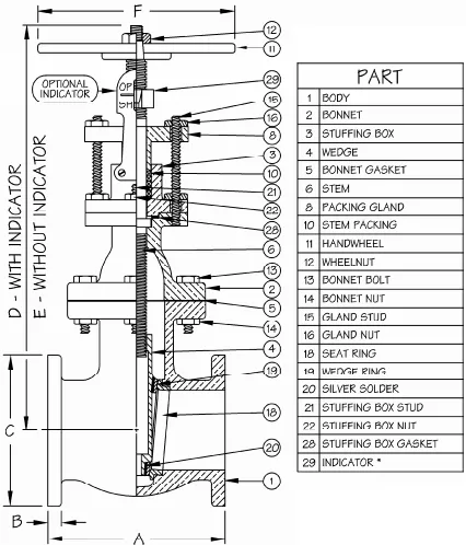
Gate valve diagram showing the key parts of a gate valve for piping
WEDGE TYPES
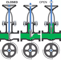
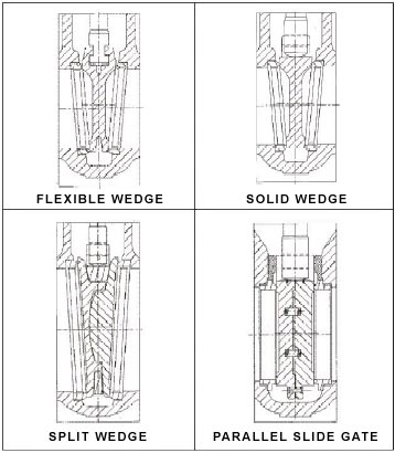
The image below shows how the gate valve wedge opens and closes the flow of the fluid by application of a vertical movement (which can be manual or operated by an actuator).
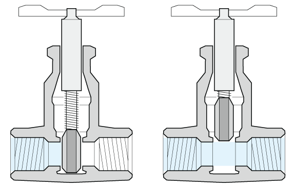
The wedge is positioned between two parallel (or oblique) seats which are perpendicular to the flow. The fluid flows horizontally through gate valves and is not subject to pressure drops. Wedges can be of different types:
- “solid-wedge” (in this case, the wedge is manufactured with a solid piece of steel)
- “flexible-wedge” (in this case the disc features cuts around its perimeter to enhance the ability of the valve to correct changes in the angle between the seats)
- “split-wedge” (two pieces construction disc, to enforce self-alignment of the wedge on the seats)
- “parallel-slide wedge“
STEM TYPES
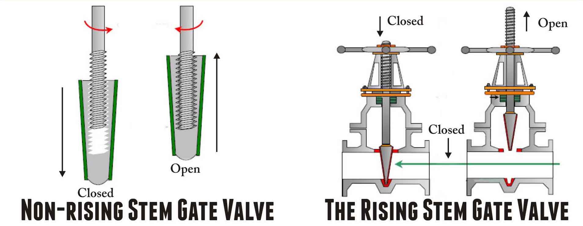
A gate valve may have a rising stem (in this case, the stem rises above the handwheel if the valve is opened) or a non-rising stem (the stem doesn’t move above the valve when it is opened).
GATE VALVE DIAGRAM
The gate valve diagram shows the standard assembly drawing of a gate valve. Many design variations are possible, depending on the gate valve parts configuration:
- body material construction: forged or cast
- bonnet design and connection: can be standard or pressure seal (high-pressure gate valves), bolted/welded bonnet, etc.
- ends connection: gate valves are available with multiple valves ends designs (socket weld and threaded for forged gate valves and butt weld for cast body gate valves)
- wedge type (solid/flexible/split/parallel slide): see details below in this article
- stem type (rising/ non-rising): see details below
- manufacturing norm: API vs EN gate valves have slightly different designs
- type of valve operation: manual, gear or pneumatic/hydraulic/electric actuation
- etc.
OS&Y VS. IS&Y DESIGN
It is very frequent to see the term “OS&Y” associated with gate valves.
This term means that when the handle of a gate valve is rotated to open or close the valve, it directly raises and lowers the disc by interacting with the stem of the valve.
In an “OS&Y gate valve”, the stem of the valve itself raises and lowers outside the body of the valve in a very visible way, while the handle remains in a fixed position.
When the stem raises, the disc inside the body of the valve rises from the seat letting the fluid flow through the valve (valve in open position).
Therefore with an OS&Y gate valve, the actual position of a valve (closed or open) is always evident to the operators.
Differently, the valve position is not immediately visible for “IS&Y gate valves” (inside screw and yoke), as the stem of the valve does not raise or lowers outside the valve when the handle is rotated.
